HOVERCRAFT DESIGN IMPROVEMENT
Investigating hovercraft airflow through CFD, CAD design, analytical calculations, and experimental testing.
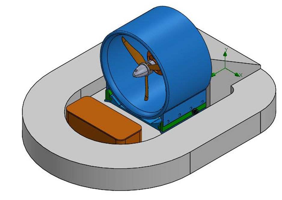
Hovercraft CAD model
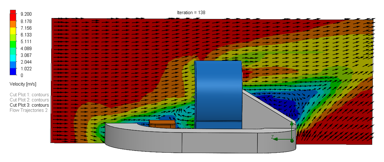
External velocity profile showing the airflow around the hovercraft.
Flow Analysis
I used SolidWorks Flow Simulation to investigate the airflow around the hovercraft and identify areas of flow separation, recirculation, and high vorticity. The CFD results helped us understand how the existing geometry was affecting the airflow and provided a starting point for developing a different flow-splitter design.
Design & Development
Based on the flow analysis, I designed a new flow splitter using two radius bends instead of the original sharp T-bend. The idea was to create a smoother transition for the airflow and reduce the losses caused by the sharp change in flow direction.
The redesigned geometry also used a fixed splitter angle of 10°, with the curved pathways intended to reduce flow separation and recirculation before the airflow entered the skirt.
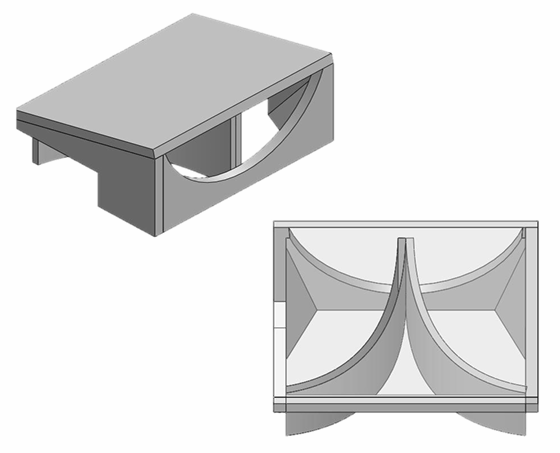
CAD model of the redesigned flow splitter with two radius bends. (Isometric and Top View)
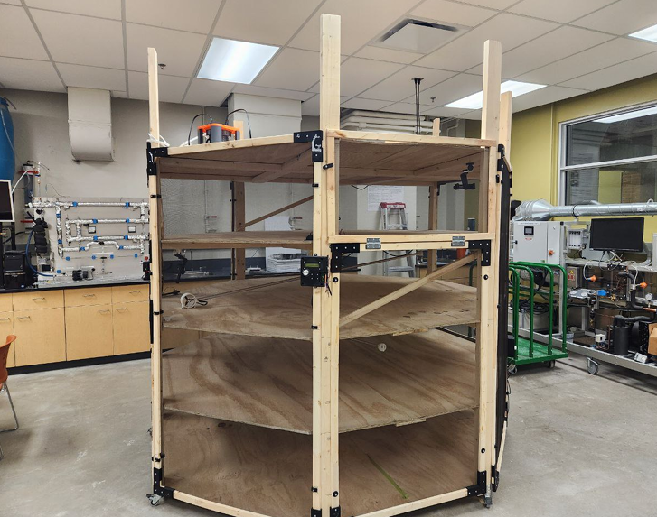
Experimental test station used to evaluate hovercraft velocity and static thrust.
The CAD model was used to develop and evaluate the proposed geometry, but the final 3D component used for physical testing was fabricated separately rather than directly from the CAD model.
Testing & Results
The redesigned hovercraft was evaluated experimentally using the same general test setup as the original configuration. The test station was used to measure the hovercraft's velocity and static thrust, allowing the redesigned configuration to be compared against the original. Twelve trials were conducted for the redesigned configuration
6.25 m/s → 5.20 m/s
16.8% decrease in measured velocity
The project challenge
The project focused on investigating the airflow behaviour of a small-scale hovercraft and determining whether changes to the flow splitter could improve its overall performance. Our team identified the flow splitter as an area where significant flow separation and recirculation were occurring, particularly around the sharp T-bend at the skirt entryway. I worked on the CFD analysis of the external flow and on developing a redesigned flow-splitter concept to address these losses.
Understanding the Results
Although the redesigned flow splitter reduced the losses associated with the original sharp T-bend, the overall velocity of the hovercraft decreased.
The main reason was the way the single-fan system divided airflow between lift and propulsion. By reducing the losses in the flow path, the redesigned geometry increased the escape velocity and the amount of airflow required to maintain the air cushion. This meant that a greater portion of the available airflow was being used for lift, leaving less available for propulsion.
Analytically, the redesigned geometry increased the calculated escape velocity from 10.83 m/s to 13.90 m/s, but this also increased the minimum volumetric flow rate required for the lift system from 0.0119 m³/s to 0.0152 m³/s. The resulting predicted hovercraft velocity decreased from 6.77 m/s to 5.33 m/s.
Engineering Takeaways
CFD needs to be connected to the whole system
The CFD results helped identify flow losses and showed that the redesigned geometry produced smoother internal airflow. However, improving the flow in one part of the system did not necessarily improve the overall performance of the hovercraft.
Analytical calculations helped explain the result
The analytical model showed that the redesigned flow splitter would require more airflow for the lift system. This helped explain why the hovercraft's predicted velocity decreased even though the flow losses were reduced.
Testing is what ultimately matters
The physical testing showed that the redesigned hovercraft reached a lower velocity than the original. This gave us a measurable way to evaluate the design and showed the importance of validating engineering decisions experimentally.